I was working on a project which involves an RTC (Real Time Clock). These RTCs are used in mostly all devices which keep time. And you know, there are a lot of these devices out there. From your wrist watch, to you wall clock or radio alarm clock next to your bed, RTCs are used everywhere.
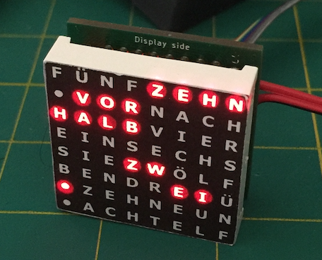
My idea was to build a very small word clock using these 8×8 common cathode LED matrix modules. You don’t know what a word clock is? Well, it’s a clock which tells you the time by reading words, such as “It is half past nine o’clock”. Each LED of the matrix is assigned to a specific character or word for the clock and the microcontroller coordinates to light up the required LEDs in order to tell the time.
Sounds complicated, is actually pretty easy – or at least it should be.
Controlling the display was indeed easy, just installed the LedController library into the Arduino IDE and used some adjusted example code.
Luckily I’m not the first person who has the idea of a word clock from these 8×8 LED matrix displays, actually I saw them on Thingiverse and though that might be a cool project. Designing the word matrix is complicated, you have 64 characters to display several words (all the hours, ten, five, past, before, half, and so on). I said luckily because someone already did most of the effort in creating a matrix for a German layout. I just had to rearrange some characters.
Now to the easiest part: Getting and setting the time. I thought once I can control the display to light up the required words to tell the time, getting the time can’t be too difficult.
Getting a time was not hard, but constantly getting the correct time was. I had the issue, that my used RTC IC (Maxim DS3231M) lost several seconds within just 10 minutes. The datasheet said, the IC is so accurate, it looses just a few seconds a year. So it was clear to me, that something was wrong.
At this time I already had ordered and manufactured 40 PCBs in China, because I though getting the time is no big deal…
Alternative design
I had an alternative design which uses the DS1307 (a very cheap and common RTC) together with an external 32.768Hz 5ppm crystal. Yeah, 5ppm, that should be very accurate. However, got the same bad results. Just after a few minutes, the time was off for seconds. Complete unacceptable!
In my desperate need of a reason, I set up a simple Arduino Uno with a ready-made DS1307 breakout board. These boards can be bought in China for less than one Euro. I though this has to be as incorrect as my built, because I used (probably) a better 5ppm crystal or even the DS3231M.
Unfortunately, the time which is got from the breakout board, was spot on, for several hours. I left this running for one day and after that day, the time was maybe one second off – I guess ok for the DS1307 which some unknown crystal.
I did a lot of further testing. I soldered the DS3231M IC (which is a SOP-8 version of the DS3231) onto a small SOP to DIP breakout board and connected that with my PCB. I though maybe the MAX7129 which I used to multiplex the LED matrix causes some interference with the RTC. It seemed to work more reliable when the IC is further away from the other parts of the PCB, however, still not as accurate as advertised (or promised) in the datasheet of the RTC.
Finally, a hint into the right direction
I think it was the DS3231M datasheet, which I checked once more. In the datasheet, Maxim wrote, that a decoupling capacitor is recommended, yeah I know. I had this on my PCB and it’s properly populated on my board. Usually I place one 100nF ceramic capacitor always to any IC on my board – of course MCUs for example might even have multiple for each power rail.
However, I was also checking the MAX7219 datasheet and I noticed something… The datasheet said, a 100nF and a 10uF capacitor is required for the IC to prevent voltage drops when the display is for example refreshed (a lot of LEDs are turned off and on at the same time). Hmm, could that be the issue?!
I piggy-backed the existing 100nF capacitor next to the MAX7219 and soldered the 10uF capacitor on top. No problem, I was using 0805 SMC components.
And what should I say… The clock was absolutely stunningly accurate. It was running for days without noticeable inaccuracy! That was a crazy lesson for me to realize, that even a small capacitor can cause such issues!
Not so fast… The next issue!
I was happy again, the clock was running properly and I kept it running for several days on my desk until I noticed something strange. It was approx. 10AM in the morning when the clock suddenly displayed around 5PM. In my shock, i pulled the power cable and plugged it back in – the correct time was back! I said to myself “didn’t see it!”.
You may already guess it… it was not the last time the issue occurred. Just one day after, the LED matrix again showed the wrong time, surprisingly again a little bit after 5PM. This time I got angry, because it seems to be a bug that is not random, it happens and it is real. How hard can it be to create a clock? Get accurate time? I started a rant with myself!
Later, I was debugging and checking the Time and DS1307RTC library in every detail. Tried to find the cause, why the clock displays 5PM every now and then.
Finally, I found, that if the RTC (which is connected via i2c bus to the MCU) does not reply, some 0xFF values are sent to the MCU which will be interpreted as weird numbers, 165:165:85h. And that time is then converted somehow into 5PM 17 minutes with my code, resulting in the wrong displayed time. With the next RTC.get(), then time is displayed again correct.
Why does the RTC sometimes delivers the wrong time?! Oh boy, again such a dumb thing…
I was running the clock with bare jumper wires to provide power to my PCB. It was not soldered, no connector, just power cables loosely plugged into some vias on the PCB. I thought “hey, if the power connection gets interrupted, no issue, the RTC keeps running on battery”.
Yeah basically that seems to be true, but I guess it turns out, that this was an issue. I’m saying “guess”, because right now I still test the clock with soldered power wires instead. Since I soldered the power wires to the PCB, the time was always correct, no more issues. Right now, I can see, I have the RTC under control – at that was harder than expected.
Hats off for all the people out there creating absolute reliable things which just do what they should do, even if it’s just a clock!
PS: Later I also found this excellent application note from Maxim Integrated, telling, that the Maxim RTCs have a startup sequence which takes 2 seconds after providing Vcc. Within that sequence it’s not recommended to initiate a i2c connection (what I did). So I also changed the code to wait 2 seconds on power up, before the RTC is queried for the current time.
PS2: If someone really saw this post and read it completely, I would happy to hear about that in the comments section below. Tell me, what kind of issues have you come across when you though: That should be an easy task to do…